Friday, September 17, 2010
The Pigments (or, If At First You Don’t Succeed)
At one time, I would make my own pigment dust, by using a set of the soft chalk pastels that you get at an art supply store, and running the stick against some 150-grit sandpaper to make a dust. With these sets, you can make infinite colors and shades, depending on what you wanted. One thing about these too, is because of the way they powder, they are fairly coarse, compared to the ready-made pigments that are on the market now. What the coarser stuff gains is that when you Dullcote it after applying, it tends to stay more of a dust-dirt without fully going into solution, like the finer-ground ready-made product. The downside to using the ‘grind it yourself’ method is the mess that comes with it, as the dust does go everywhere.
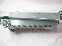
For the Tiger, I decided to use some Tamiya Weathering Master Soot, and pigments from the MIG Productions “Fresh Mud” set. I have used these before, and they are okay, but do go into solution more readily than what the chalks will. The appearance is more of a subtle, stained, look, than the chalks. I applied the dirt liberally to the underside, the lower areas, wheels, tracks, and at the rear of the upper hull, around the engine grills and fuel fillers. I also applied it to the front mudguards and side fenders at the edges.
When I was done, I applied several light passes of Dullcote. Then the cussing began. I was satisfied with the roadwheels and tracks, but everywhere else had the appearance that it had been hit with a soot cannon, or a kindergartener with black finger paint.
I considered going back over the soot spots with a lighter pastel, and just hide it. Another part of me doubted that would look any better, so I decided repainting the sooty mess would be the best option.
I taped off all the areas that didn’t need repainting. This included the wheels and tracks, the bulk of the upper hull, and the turret with the exception of the end of the muzzle. Using my airbrush, I shot these over, and lightened as needed. Then I pulled off the tape, and shot these areas with Future, to get ready for washing…..again. That being said, if there are other areas where a touch-up would help, now is the time to do it.
More words of caution. Be careful when you tape, so that none of the little bits get knocked off. Also, I was fairly lucky, as the bulk of the detail painting was taped over, such as the tools, hull machine gun, cables, etc. The only detail piece that will need painted again is the jack on the rear, saving a lot of work.
The repainted sections look much better, and I was pleased with the result. It is significantly lighter than the areas that have been washed and clear coated, but this will even out once I wash the freshly painted touch-up sections. This is where remembering what paints and shades and ratios comes in handy.
Next up is to wash, detail paint, and drybrush to match the rest of the Tiger
Thursday, September 16, 2010
Drybrushing
Since the Olive Drab is a little lighter than what I normally paint, I only did one pass for highlighting. Typically, I will do up to three passes, going slightly lighter each time, until I hit a shade that is about 25% lighter than what I started with.
For the Olive Drab of this Tiger, I mixed 90% Model Master Acryl Olive Drab 4728 (my base color), with 5% Vallejo 913 Yellow Ochre, and 5% Flat White. Add a little water to this to retard the drying, and I got started. On something this big, it is important to remember the mix, as it will take a little longer than one sitting to get it all done.
Using a ¼” flat brush, I removed almost all paint from the brush onto a paper towel, and hit the high points, panel lines, bolt heads, rivets, etc. In some smaller areas I also used a 3/0 brush. Once all this was complete, I used a very light dry brush of Metallic Grey at spots where paint would get rubbed off, such as grab handles. A little of this goes a long way.
I also touched-up the metal bits on the cables and pioneer tools with a few different metallic shades to vary the color.
Once drybrushing was complete, I again shot a light coat of Dullcote over the Tiger. This will protect the work and get it ready for the next step, which is to apply a pastel dusting. I also put the tracks on at this point.
The Washes
I have adopted the technique of dot filters, which are now fairly popular, and seen in the modeling magazines with some frequency. I start with dotting the surface in irregular intervals using the four colors of oil paint that I have chosen. For the top and upper surfaces, I used about 50% Yellow, 30% Burnt Umber, and the balance in Ultramarine Blue and Crimson Red. The Red and Blue are so strong, that a little of them goes a long way. As I worked my way down the tank to the wheels and lower hull, I gradually shifted the ratio to where I was using almost all Burnt Umber, especially around the roadwheels and underneath the hull.
Once the dots were in place, I started to move the oil paint using a ¼” wide flat brush, dampened with clean solvent. This is important. For this to work, you need to frequently clean the brush that you are using. To move the paint, I would move and pull, especially on the vertical surfaces. In tighter areas, I would use the same technique, but would use a 3/0 brush. I worked my way around the entire kit, and then started over, using a slightly lighter technique for the second pass. The third pass was even lighter. Using this method, it took about four passes to get the effect that I liked. On some of the vertical surfaces, where the effect of rain and water could be seen, I left some slight streaking for effect.
In other areas where I wanted more of a dirty build-up look, I allowed a little more of the thinner to remain in the brush, and this will give the oil paint the ability to run into crevices and lines, such as the inside of the rim of the roadwheels. This will take the place of a pin wash so that I do not have to go around again to get into these panel lines. The other part that will help emphasize the panel line and detail will come a little later, after I apply the dustcoat pigments. I spray a sealant over the pigments, and this causes them to go slightly into solution, which makes them do the same thing as a pin wash. But, more details on that, later.
I have also used on other kits the method known as “Sludge Wash”. This works great too, but because of the amount of detail and fiddly parts on the Tiger, I didn’t want to break anything when rubbing off the excess sludge. So oil washes work best here.
Once I was happy with the oil wash, I let it dry overnight, and then sprayed a slight coat of Dullcote over the Tiger. This will protect the washes from being smeared during handling while I am dry brushing, which is the next step.
Friday, September 3, 2010
The Tracks
I assembled per Step 24 of the instructions, and they do go together easily. The instructions call for 72 links per side, but I tested the fit, and added one more per side to get the sag appearance that I liked. The fit will also be influenced by the final position of the rear shaft (Step 4)
Once assembled, I cleaned the tracks with soap and water, and let them fully dry. The material these are made out of made me think that enamel paint would bite better than acrylic.
First step in painting was to prime with automotive spray can primer. This was followed by fully coating with Flat Black spray from a can. I let these dry for a full day. The first “real” coat of paint was a thin mix of 50/50 Flat Black and Tamiya Gun Metal, thinned to 50%. Once dry, I followed with a mixture of 50/50 Testors enamel Leather and Rust, and thinned this down to about 30% paint and 70% thinner. I shot this through my airbrush, and the idea is to get down into the crevices, slop this around, and not let it be uniform. The look I am trying to copy is that of random steel scaling. Before this coat had a chance to dry, I dusted with the spray can Flat Black, then quickly dusted with a shot of thinner through my airbrush.
From all of this mess, I had the appearance of unpolished iron; a little sheen in spots, black in others, with dirty rust in the crevices. Last step was to dry brush the high spots, where the tracks would get polished, with Testors enamel Aluminum. I don’t use Silver, because I think that it is a little too shiny. The outside of the tracks are easy, and on the inside, I only hit the guide horns and the outer edge. I didn’t want to dry brush where the pin marks and numbers are, as it would only call more attention to them.
One other tip: as the paint dries in each step, it will get down into the seams in each link, and start to stiffen. After every step, and a few spots in-between, you need to curl the track in each direction to keep this from happening. I did mine after each step in the painting process once it was dry to the touch. It also kept the paint from flaking, and if you have ever done a tank with rubber band style tracks that were painted with acrylics, you know exactly what I mean.
Saturday, July 31, 2010
Details, Clear Coat, and Decals
Tuesday, July 27, 2010
Painting the Turret
Saturday, July 24, 2010
The Turret
The storage bin needs some work, too. The mount clips at the top of the bin, Part C28, need removed and filled/sanded. Same is true for the locating slots in the Turret roof. Again, this bin configuration is correct for later versions, but not the Tunisian. Instead, it used two braces riveted to each side of the bin, and welded to the Turret. When I filled and sanded the brace area on the existing lid, I also removed the existing small rivet detail on the lid, as the early bins did not have this feature. After gluing the bin in place, I fabricated the straps on each side using 0.020 x 0.060" styrene. I added three Grandt Line bolt heads on each brace, on the bin-side, as on the real thing. I cannot emphasize enough how fantastic these Grandt Line detail pieces are!
I also cut two very small pieces of 0.010" thick styrene, and glued and bent these to represent the latches on each bin lid. A very small piece of rod was glued to these to represent the latch pin.
The ventilator, Part D18, was left alone. In some photos an armored cover is present, but since the 1/25 scale kit does not come with one, I left it as-is. I did check other 1/25 scale kits, such as the Academy Panther, but nothing was appropriate.
The cupola is accurate, and only a few small details were added. I drilled the rain drainage holes using a very small bit in my pin vise where these were present. Two very small sections of rod were attached where these belong for the sunshade. From the commander's position viewing forward, these would be at the 11 o'clock and 5 o'clock positions. A great photo of this can be found on Page 54 of The Modeler's Guide to the Tiger Tank (Stansell).
The smoke grenade launcher held the most work of any Turret item. I assembled them per the instructions, with a few modifications. I installed the bracket, Part C38, to each side, and filled the small gaps on the Turret roof. next, I drilled a small hole just aft for the main conduit run where it enters the roof. The bracket for each launcher (6 in total) were drilled for conduit at the rear of the launcher, Part C29. I bored through into Part C4, which will allow the wire to feed into the rear.
Before terminating any wire, I took three small pieces of copper wire, and a 0.010 piece of lead solder, and sandwiched these between two pieces of thin, narrow styrene strip, cementing the strip together with super glue. Once dry, I cut the strip as small as possible, thus forming a junction box. This was glued to the inside of the main bracket, Part C38, where it would be minimally visible.
Before mounting the launchers to the main bracket, I cut the slot that is evident on the discharge end. It runs across the radius in two spots of the tube. I also cut a thin section of rod and inserted it into three of the launchers to represent loaded grenades. Once done, I glued these to the main bracket. The feed wires were then trimmed, and the small copper wires fed into the hole in each launcher, while the lead solder was trimmed and fed into the hole in the roof.
The main gun was installed per the instructions after cleaning and sanding. I had debated making, or having made, a main gun out of turned aluminum, but really, the Tamiya part is pretty good. I glued the gun in place, so the elevation may not be changed, at a permanent elevation of about 20-degrees. This helps hide the gap at the top of the Mantlet, which is pretty significant on this kit. It makes it look more aggressive, too.
Lastly, the Turret was coated with Tamiya white primer from the bottle, and hit with a stiff brush when it was partially dry, which gives it that stippled appearance that the steel exhibited from casting and crude rolling. On to primer and painting. Assembly is complete at this point.
Wednesday, July 7, 2010
Painting The Hull and Adding the Roadwheels
I started with spraying all surfaces with black automotive primer. I let this dry 24 hours, then checked for any areas that needed sanding. A few light touch-ups, and then I coated all the bottom surfaces with Vallejo 70995 German Grey. The easiest way is to turn the Hull upside-down, and get a good coat everywhere. Turn the Hull over, and concentrate on the lower parts, such as around the torsion bars, return rollers, and sprockets. At the same time, I also sprayed the roadwheels. That being said, the roadwheels that I am using are salvaged, and already fully assembled, so it takes a little more effort to spray these.
After allowing the German Grey to dry for a day, I followed with my main color, Model Master Acryl 4728 Olive Drab. The Tigers sent to Tunisia were originally German Grey, and sources indicate that these were over sprayed with captured American olive drab. I decided to go with this, and if these were sprayed in forward areas near combat, then it seems logical to me that there would be areas that couldn't be painted with the olive drab. This would include the bottom plate of the Hull, inside surfaces of the roadwheels, under the fenders and sponsons, etc.
To try to duplicate this, I kept the Tiger right-side up, and sprayed with the olive drab with this thought in mind. In other words, imagine yourself trying to paint a real one, and what you could reach. For the roadwheels, I simply set them down and sprayed them in olive drab with the outside face-up. I wanted to spray the roadwheels off of the tank, which will allow easier painting of the tires.
Painting the tires is simple, but time consuming. If these were not already assembled, I would have sprayed them through a circle template. Since they were in one piece, I used Vallejo 70862 Black Grey at a ratio of 10 parts paint to 7 parts water. Thinned like this, it will flow easily up to the wheel rim where the tire meets the rim. This lets capillary action pull the paint from the brush and flow around the rim.
Once all tires were finished, I mounted them per the instructions. Pay attention to Step 5 of the instructions, as it is easy to get confused during weaving of the roadwheels together. I did put a few nicks in spots during this assembly, which I touched-up when I was finished. This wasn't unexpected, and I also needed to paint the Polycaps (Part M7) that hold the wheels in place. Make sure, too, that these Polycaps are pushed into place and seated as deeply as they can go.
So far, so good. One other comment, and that is that any fading/shading of the olive drab will be done once the Turret is complete and on the tank. On to the Turret....
Saturday, June 26, 2010
Top Hull Details, Part 2
The other cable was constructed and installed, then mounting clamps constructed. All were done just like the previous details. Grandt Line wing nuts were added to each clamp. Check photos from your reference for where to place the wing nut. It is just too difficult to see in my picture. Those things are tiny!
The fenders were installed on the right side of the hull, after separating them into individual pieces and cleaning them up.
To finish work on the hull, I added the Feifel air cleaner hoses. These were re-installed as per the kit instructions, after removing seams and cleaning them up. Thankfully, the previous builder did a nice job cutting the vinyl tube to the correct length, so that I had no problems. One thing to point out, here. On the Feifel, between the two cans on each side, is a nipple which I believe may have been an access/clean-out plug. Photos I have show a small, looped, braided cable that is connected to this nipple, which must be a grab-loop to pull out this plug. I didn't add this. Also, the Feifel hoses are flanged between the hard pipe and the hoses, and this appears as a metal, square insert in photos. I didn't add this, either.
Once the Feifel work was complete, I gave the assembly one last check, then sprayed it completely with black automotive primer from a spray can. Here's a tip, too. Shoot a little inside the hull, towards the back of the hull. This will help hide the fact that there is nothing under the grills, and once the turret is in place, it will make it difficult to see inside.
A few spots to sand after priming, and it is time to move this along. While this was going on, I also prepared the road wheels for painting. These had been painted previously, along with the tires. (actually, they were the only thing that the previous builder had painted on the entire tank exterior) To get these ready, I put them in a small container, filled it with undiluted Mr. Clean, let them sit overnight, then took a Scotchbrite scouring sponge to them. The old paint easily came off, then they were rinsed and allowed to dry.
Sunday, June 6, 2010
Top Hull Details, Part 1
Work progressed on the Upper Hull, with the addition of the engine grilles. These are from Aber, and were purchased through Pacific Coast Models. They are gorgeous.
Front Headlights
I used 0.020" styrene sheet, cut into a rough square, big enough for the mount. The brace that serves to hold this up is a triangle cut from the same material, although small enough that its' edge does not come out to the edge of the mount for the light. I glued these in place, and slightly rounded the corners of the mount. Critics may see other references where this new mount was an elaborate affair, constructed of angle iron and complex bends. Since this was field-fabricated, I think mine would be appropriate, too.
The kit headlights were used, although the long, narrow post was cut-off, and a short, thicker rod replaced it. This is to represent the socket mount. Thin strips were installed in an "+" pattern, with the post in the center, in a scale representation of what the male-female connection looked like. A hole was drilled in the left side of each light for the conduit entry. The junction box exiting the hull was duplicated with rod that was rounded on top like the real one. A hole was also drilled in each junction box for the conduit.
The conduit run is a 0.020" piece of lead solder from Hudson and Allen that I had as spare. First, I glued this into the junction box, and ran across the front lip of the top hull, and made sharp bends to get this to the light, where I cut the solder to length, and glued it into the light. The final touch was a very small piece of thin foil, as the clip that holds the conduit in place just after it makes the 90-degree bend to go down over the glacis.
Tuesday, June 1, 2010
Front Hull
Monday, May 31, 2010
Left-Side Lower Hull
After a hiatus; back to the project. (I felt compelled to finish SOMETHING, so I pulled out the 1/35 Dragon T-34 1941, and the Dragon King Tiger with Zimmerit that have been on the shelf)
Early on, I had removed the fenders on both sides, and filled and sanded the holes for the mounting pins. The fenders are actually four separate pieces, but Tamiya molds these as a single unit. I cut mine at the panel lines between, and thinned out the edges for better scale thickness. Also, there is a triangle-shaped fillet at each end of the single molded fender that shouldn’t be there. My guess is that this helps in the molding process. Take this out, too.
I mounted the fenders back in their original position, and to help things out, I mounted a strip of .010” x .030” plastic along what will be the bottom of the fender mount where it meets the hull. This won’t be seen, and it will help keep the fenders in position as the glue dries.
The prominent feature on the left of the hull is a thin steel cable that was used to pull tracks together, and to change tracks. Tamiya, in the original kit, supplied the wire, but it is stiff. I substituted .020 lead solder. Be careful, though, as this stuff is easily torn, and wash your hands when you are done.
Check your references for this cable, too. There were a number of different placements of the clips and how the cable was mounted. For our Tiger, the Tamiya instructions are fairly accurate, with one exception: I needed one more mounting pin to the upper right side, where the eyelet mounts. I strung the cable, then super glued as I went. For the ends and eyes, I used a short section of plastic rod, and the eye was made of thin-sliced plastic tube. When this is all glued together, I am pleased with the visual representation. Lastly, the eyes of the cable have a clamp that holds it in place, so to simulate that, I used a thin, narrow piece of excess brass, and bent it into a J-shape. The small part of the J goes through the eye, and the brass is mounted to the top of the pin. Yeah, confusing, but the picture should help. Is it 100% accurate? Not really, but I think it is a good visual simulation.
Also on the Tamiya mold, the very significant wells seam at the front and side plates is missing. I scribed this using a sharp blade and guide to the appropriate size, then used glue to soften the plastic. After waiting a few minutes, I hit it with the blade again. After it dried, a quick sanding took the high points off, and left me with a decent-looking weld seam.
Saturday, April 24, 2010
Fabricating the Exhaust Shields
The exhaust shields for my Tiger were the first installed, and field-fabricated by repair crews. That being said, they were thin, and certainly designed for utility instead of cosmetic value. Keep in mind, they probably didn't have an elaborate bending brake, and cut the shapes with a torch. As you fabricate yours, keep this in mind. On the 1/35th scale parts I have seen that are of this type of shield, they have a very delicate louver cut and bended, which I doubt the field crews would have done.
What you need are a sharp pair of scissors, knife with sharp #11 blades, needle files, and one thing that really helped me was a pair of drafting dividers. I used the dividers to scale out the size this shield should be, and transfer the dimensions to a pattern. Being the nice guy that I am, my sketch of the part is above the text.
I used 0.010" brass sheet for the part. Follow the sketch, and with scissors, cut the overall size. Then, cut the side slots where the shield fits over the 3-bolt exhaust cover on each side. Round the corners where I have indicated using a needle file. To cut the vent slots, I marked the location on the sheet with a pencil, and then used a diamond cut-off wheel in my Dremel at a slow speed. Brace the part, and also your hand that is holding the Dremel. Take your time, and it should be straight. Cutting the slots will leave some burrs around the hole; you can clean these with a sharp #11 blade. Use a flat needle file to smooth out everything. Lastly, align the fold line on something that has a nice, straight edge, and slowly bend. The bend should be slightly less than 90-degrees. The shield is wider where it mounts to the rear hull.
To mount this on the Tiger, I glue a very narrow strip of 0.010" plastic, about 1/8" wide x 1/2" long, going up vertically from the middle of the 3-bolt exhaust mount on each side. This is a little bit of my imaginative engineering. Namely; the real field crews had to have something other than the hull-rear to weld this sheet shield to. Hey-it looks right to me. Then, using superglue, glue the shield in place. You may need to trim slightly to get a good fit-then try it again. Also, since these shields were sheet metal, they were beaten up easily. Now is a good time to take a plier and bend them a little, if so desired. Hint: If you have a slight fit problem, this can help/cover it up. If you do it right, it should look correct; like the photo at the top of the post.
To finish up in the rear, I reinstalled the jack, after cleaning it up. The crank for the starter (C32) is pretty weak, and was broken, so it was replaced with brass rod that was bent to shape. I removed the mounts for the crank from the plastic piece, and drilled these out with a pin vise to accept the new brass crank. I also saved the square socket from the end of the plastic crank and attached it to the brass replacement. Watch out for the starter plate (D2). On later Tigers, Tamiya has this correct in a straight up-and-down mount. But on the very early Tigers, this was a diagonal mount, so I reinstalled the starter plate diagonally. With this, I was done on the rear.
Saturday, April 17, 2010
Exhaust, Part 2
I removed the installed mufflers, (Parts D1 and D15). This was a headache. Tube glue and huge locating holes. I filled and sanded the holes in the rear hull, and then repaired where needed on part D15. To correct the muffler, I removed part D17, the raised deflector, as it wasn't on this version. After I cut the legs for this, I simply cleaned the recess in the top of the muffler, and filled it using rod, cut into a disc, about 1.5 mm thick. I wanted this to be flat across the top of the muffler. Then, I took a thin slice of 0.16" rod, and glued it in the center of the muffler-this will be the exhaust flapper. The flapper looks a little concave in the drawings that I have, so I took 320-grit, and rounded it a little on the edges.
For the flapper hinge, I took a very sharp #11 blade, and cut a notch in the flapper that I had just made, starting at the center of the flapper, and going to the edge. The hinge should be in the middle of the exhaust rear, and I am just trying to simulate a hinge. A small section of plastic rod cut to length, serves as the pin.
There are five bolts that need represented, and in the real Tiger, these were a recessed screw. Yeah; I'm not doing that. Instead, I am going with a raised bolt-head, which will give about the same visual effect. To do this, I cut 5 pieces of very small rod, about 1" long. Here's a tip: Make sure that the ends of your cut are dead flat and square, using a very sharp blade. This will make the next step easier.
To get the bolt pattern, I dabbed a little liquid glue on one end of the 1" piece of rod, and using tweezers, attached it to the area of the muffler between the outer diameter and the flapper. I glued the first piece directly opposite the hinge pin, and then one on each side of the hinge pin. The last two pieces were affixed in-between these. Once the glue is dry-and I mean really dry-I used a very sharp side-cutter, and cut these off to where they are just barely above the surface of the top of the exhaust.
One thing that I need to point out, too. My exhausts are knowingly too tall, but it was done for the ease of construction. Here's why. The rod inserted in the existing exhaust made my life easier, but in reality, the outer walls of the exhaust should have been trimmed down 1.5 mm to where the molded top was. My method, like I said, made my life easier, but if you do the math, if this were a real Tiger, my correction would be 4" taller than it should. I'm not about to fuss over that, though.
So now that the mufflers are reinstalled, it is time to make those louvered exhaust shields. Time to find an empty aluminum can....
Saturday, March 27, 2010
Correcting the Exhaust (and Waiting on Parts)
The dual exhausts on the kit, parts D1, D15, are accurate for the early Tiger. However, Part D17 is an elevated outlet cover on four short legs above the exhaust outlet. My references say this wasn't installed until sometime in early-mid 1943, which is a little late for the Tunisian Tiger. So I will delete that. One thing that is missing from the exhaust is a hinged flapper cover for each exhaust, that by this time was standard on the Tiger. The flappers will be scratchbuilt using some Plastruct rod, cut to size. Here is where I am waiting on parts.
The rear exhaust was also equipped with sheet metal shields. The original shields were field-installed by maintenance crews in Tunisia, and you can see these both as fully-rounded, or squared corner. My photos say either is correct, and should also have three louvers spaced in the top half of each side of this shield. Since it will be easier to form these using the squared-corner design, I will go with that one. I will fabricate these out of thin aluminum, which means another trip to the hobby store for supplies. That being said, the Tamiya-supplied shields (Part D12) are perfect and nicely done for any version other than the very early Tiger 1.
Here's a tip, too. While I am back here doing some work, there are some very large mounting holes in the rear hull that I will fill and sand, too.
Another thought, while waiting for parts, is that of the engine grills and tool clamps, which are still somewhere in process from Roll Models. In other words, until this stuff shows up, work on the lower hull is coming to a screeching halt. More to follow.....
Sunday, March 14, 2010
Attaching The Top Deck to The Lower Hull
Sure, this sounds easy. But like Billy Mays always said, “Wait…there’s more!”
First off, The Top Deck (from Step 15 of the Instructions) will be warped. All of mine are to some extent, and this one is no different. You will need to get some heavy rubber bands, and in my case, some small Irwin Quick-Grip clamps, ready. Make sure that the pin marks on the edges of the Top Deck, especially at each rear side, are sanded smooth.
Also, the Front Glacis, Part B3, has two significant pin marks at the top-rear, that should be filled and sanded before you mount the Top Deck. Once these are addressed, run a bead of plastic cement around the full area of the Lower Hull sides where the Top Deck will meet, and inside the front and rear channel for the Top Deck. Insert the Top Deck into the channel in the Front Glacis (B3), then pull it down into the rear channel, and start matching up along the sides. Clamp and band to keep the seam as even as possible. On mine, rubber bands worked well, and they were used around the hull in both side-to-side and end-to-end fashion. At the areas where the warpage was worse, I had to apply slight pressure with a clamp at the right front corner, and the left side just ahead of the engine deck. Once the glue dries, inspect your seam line, fill as needed, and sand smooth.
With all of the sanding done so far, weld seams will need to be re-done. After the glue is dry and the clamps come off.
There are a few things to note, too. The driver's periscope, was ignored from Step 10, since it cannot be seen from the outside. The MG 34 in the Front Glacis (F2) was removed from the ball mount (B1-B3), and the ball mount was left in place. Since this is an exterior-only build, we can mount the machine gun barrel only, after painting, from the outside. Also, at a later time, we will address the two periscopes missing from the hatches. These can also be done from the outside, since Tamiya designed no periscopes coming through the hull, anyway.
Sunday, March 7, 2010
The Front Mudguards
The front mudguards are a decent representation of the real ones, but they need improved. In real life, these were hinged on the outer 1/3, and Tamiya has this hinge molded, but it isn't great, and there is no latching mechanism like in real life. There is a very slight panel line where the two parts meet, but this should be a true cut on the ends where the hinge does not cover it. All of this could be improved, by filing off the hinge, cutting the mudguards where they should, then scratch building hinges, latches, etc. But, these mudguards weren't used until early 1943, and my Tunisian Tiger predates that, which used a different style mudguard. For the earliest Tigers, you will see an unhinged mudguard, that is angled about 10-degrees further than the angle on the front glacis, and then at the mid-point, it has a bend that sends the outer half about another 10-degrees down. These mudguards were also covered in tread plate.
It was time to get the Dremel, and with my cut-off disc, removed the existing mudguards. While there, and you will see this in the photo, it was time to smooth the cut using a file and sandpaper (320), and filling the gap that was hidden under the mudguard.
The replacement will be fabricated using sheet stock, cut to size, and with the correct angle in the middle. Then, I will cover that with scale deck plate, which is available in that scale for car models. Again, check out the local hobby shop or Roll Models. Since I don't have any deck plate, finishing the mudguards will wait.
On Accuracy and Weathering. My Opinion
Another example: On page 111 of The Guide to Tiger Tank, it has a picture of the front headlight and the etched mounting bracket they used. Apparently, the real-life bracket that they used for the example was an intricate, angle-iron based support, with miter cuts, mounting bolts, etc. It is crazy-detailed, and in scale (1/35) size, I cannot imagine what that would be like. Since I am building a Tunisian Tiger, and the headlights required the mount on the front plate, I need to use something like that. But then, since this was a field modification in real life, I just cannot imagine these field crews doing anything other than the most basic construction, which to me, would be correct, too. So on mine, it will be a representation of a simple pair of plates welded to the hull that hold the headlight up. Easier for me, and almost impossible to refute.
And weathering? Some, to me, is just completely overdone. Yes, I know that they get dirty, dusty, and muddy in real life. But unless I am putting it in a diorama, all of the caked-on mud looks silly. Plus, again in my opinion, why do you want to do all of the crazy paint detail, dry-brushing, etc., just to obscure it under mud? Again, it is about preference, but I like light weathering.
One more point is painting the thing. Take the Tunisian Tiger, for instance. These were originally in German Grey, then painted green. In the field. Which means, these crews did it using what they had. Behind the road wheels, under the fenders, hull bottom, etc., shouldn't be green, except for where over spray would hit. That is how I want to represent mine. Think Earl Scheib. And I don't get these extensive fade effects, either. Sure, it wasn't the best quality paint that was used in real life. But I see heavy sun fading being represented, with the "pre-shading, post-shading, spraying almost white in panel centers, blah-blah-blah", and I shake my head. Again, to me it is overdone, and I make a slightly lighter top than bottom, but the real ones just didn't survive that long-especially the early ones-to get that faded. Some of them are faded more than that old '34 Ford that was parked in the meadow at my Grandpa's that was still there in the mid-80's.
Time to redirect, and get back to the build.
A Few Words About References
If you model the Tiger Tank, there are more references than you ever need. These are available via the internet, books, magazine articles, etc. Of course, you already know this. The best of these, in my opinion, is "The Modeler's Guide to The Tiger Tank", written by Patrick Stansell with Bruce Culver. It was released a few years ago, and I am not even sure where I found it, but it is incredible. Not only does it feature numerous builds (and these guys are museum-quality builders), but you will find kit resource lists, identification drawings from the real tanks, and even a disposition list of actual tank chassis numbers. Unbelievable. Here is a great link to a review of the book, via the Edmonton IPMS:
http://www.ipmsedmonton.com/April%202004web.pdf
Saturday, March 6, 2010
More on holes, and that rear axle assembly
Check out all of the holes!
Good god, did you notice all the holes in the bottom hull? Everyone else will, too. Obviously, part of a plan for radio control, but since this is a static kit, they need filled. Start with the bottom of the sponsons. Easiest way to fill all of this is to take very thin sheet, cut it to size, and use it like a veneer. If you do this right, it will never be seen when you are done. The fenders will hide it.
Left Side Lower Hull
The left side has a wire towrope held in place by some clips. In the instructions, this is Step 14. The clips look usable, but the wire Tamiya supplies, and the piece of vinyl to hold the end, is dicey. The wire is very stiff steel, so when the time comes, I will replace this with copper. Softer, and easier to bend. I am saving the clips.
Getting Started
Day One. Deconstruction.
I identified the hull that I was going to use. Actually, as they were both in the same condition, it was a coin toss. All road wheels were removed, along with any other parts that needed to come off. On the rear plate, I left mufflers, starter, Fiefel air cleaners, toolbox, fenders, etc. The jack was the only thing removed. Seams were everywhere, and these were addressed. The side fenders were pulled, and these were cut and sectioned, as they should be. The mounting holes for them were filled and sanded.
On the front glacis is a mounted shovel. This is accurate, but the placement, as designed by Tamiya, can’t possibly be correct, or it would get in the way of the coaxial machine gun in the ball mount. Off came the shovel, and the mounts, and these were filled. Keep the shovel, though, for later. This is where I decided (OUCH!) that I am going to buy the Aber 25002 set of photo etch tool holders. Aber makes these for both early and late applications in 1:25 scale. Check Roll Models. While you are there, get the Tiger I grill set, too.
The Introduction (Or things that you can skip)
Will follow a dedicated build of a Tamiya 30611, German Panzerkampfwagen (SD.KFZ 181) Tiger I Ausf. E. That being said, we will just call it the Tiger. I may call it a few other things along the way. But it will be the Tiger. In 1:25 scale.
More accurately, too, this isn’t a build. It is actually a salvage operation, and herein lies a story, and then we will get started…..
The History
We all know the history of the actual tank, so I am not repeating it here. Look at another website, or as my mother always instructed, “look it up”. And that was back in the days before the Internet, which involved pulling out a 28-pound World Book Encyclopedia. We are talking about this kit, in this scale. The 1:25 scale Tiger was produced by Tamiya starting in the late 1970’s, and was one of a series of tanks in this scale. After many years, the series was discontinued.
By the mid-1990’s, these kits started to become, and still are, collectible and expensive. This is where I came in. By the late 1990’s, I decided that I would corner the market on the 1:25 Tiger, buy as many as I could, and use them for fun and profit. I pictured myself making resin parts and photo-etched grills for them (both skills which I have), and selling my wares on the Internet until I could afford that vacation home in the Caribbean with a Porsche in the driveway. Obviously, life took over, that never happened, and I have quite a few of these Tigers on a shelf in the garage, ranging in condition from new-in-the-box to complete (but poor construction, paint, etc.)
Oh, yes, and Tamiya started to re-issue the series of 1:25 tanks, starting with the Tiger. The hissing sound that you may hear is the deflating balloon, which represents the above-mentioned riches from my cornering the market.
Our Subject
The subject will be one of these Tigers from the garage-stock. More correctly, it will be two. One of my Internet purchases (via ebay), were two Tigers that someone had constructed (yes, they had two), and wanted to get rid of. When I received them, they were fully assembled, but some parts were missing. The interiors had been installed, and about 1/3 of the interior was painted. No paint on the exterior, which is a good thing. What were evident, everywhere, were the seams. No seams were sanded during the original construction. And tube glue. We all know tube glue.
Because of missing parts, and the condition of both, I decided to use the two kits to get to one decent kit. That being said, this will be a “curbside” model. The hatches are getting glued shut. The former owner’s lack of tube-glue control made such a mess of the interior, that I will salvage what I can of the interior parts, and save them for another project.
The next decision was what Tiger to model. Decals from the original do give options, including that of Michael Wittman’s tank. But I have never done a Tunisian Tiger, and wanted to do one. This model accurately puts it into the timeframe of Tigers in North Africa, which works. Plus, the Bovington Tank Museum Tiger was a Tunisian-captured tank, so the photo references are everywhere. Check out the site at http://www.tankmuseum.org/
And another thing….I am not on a mission to recreate this sucker down to the last nut and bolt. If you after that sort of thing, go to a different site. However, the point is, there are few documented builds on the 1:25 Tiger, and this thing has it’s share of issues. With the number of old 1:25 Tigers out there, and the re-issue using the same molds, the thought of sharing my experience may be helpful. Or a fore warning.
So, follow along. I will post photos as I go, and updates as I can. Along the way, be patient. I am not the world’s fastest builder, and I may throw an odd opinion, too. This is my page, after all, which leads me to this thought….
About Me
I am a professional engineer, in my mid-40’s. I modeled as a kid, and then stopped in my late teens, and picked it up again 12 years ago. I have all the tools, skills, etc., but like many people, I sell myself short. I have also somewhat given up on the thought of spending hundreds of hours on a museum-quality piece. I build mostly straight from the box, and maybe add a few items that I scratch build or modify. I hate photo-etch. My fingers and eyes don’t like it. I don’t go to contests because I don’t think that my finished kits are worthy. I do this entirely for my own enjoyment, and a few oohs and ahs from my best friend, Todd, who is a fellow enthusiast. Everyone needs a Todd, by the way.
I am blessed with a great area to do my modeling. I have a desk in an office, adjacent to the man cave, where I can set up shop, not be bothered, and turn on some music. The cat will, at times, jump up on the table, but for the most part, it is my space. And I will advise having a good selection of music in the background.
I do not have unlimited time to do my modeling. I have a job, and chores, and home repair projects, and a family, and a fiancee. More accurately, a charming, beautiful, fiancee, with an unlimited amount of patience for my hobby.
So, hopefully, you are at the point of wanting me to shut-up, and get on with it.